Conception of VLT Control System
The VLT Control System on one hand implements a highly distributed architecture and on the other hand a layered approach. On topmost layer a set of networked UNIX/Linux workstations provides the platform for high-level application software, e.g. coordination tasks, observation planning and control, user interface, data reduction and archiving, etc. At a middle layer many dedicated VMEbus systems control the various telescope, dome and instrument sub-systems, which - among others - include the axes, drives and motor controls. On these so-called Local Control Units (LCUs) run the low-level software and according device drivers, based on the VxWorks real-time operating system. An LCU communicates to the workstation layer via TCP/IP over Ethernet.
If a complex sub-system employs a micro-processor, as in the case of RMC, this is called a Target Micro-Controller (TMC). Each TMC is controlled by a superordinate LCU and usually is connected to that LCU by a field-bus. Into this system environment the RMC concept is integrated as a TMC.
The RMC Sub-System
The fundamental RMC design approach is to control a rich set of axes, like filter wheels, shutters, adjustable mirrors, focussing units, movable mechanical parts of instruments, etc. is a standardized way, despite of its diversity. The axes control flow is vertically from application software through the LCU layer to the integrated target mircro-controller in a programmatic way. Further, high value has set on fulfilling the special requirements of observational astronomy with respect to environmental conditions, thermal dissipation, vibrations, etc.
A Remote Motor Controller is always located nearby its drives and connected to its according LCU via CAN-bus and CANopen. Control via CANopen is based on the Device Profile 402 für Intelligent Drives, supplemented for ESO‘s specific RMC functions.
A Remote Motor Controller essentially includes the following components:
- Main-board which carries those hardware components which are common for all required types of motors. These are: encoder control, control logic PLD, digital and analogue inputs and outputs, tachometer interface connection, CAN interface, debugging interface, brakes control, detection of end- and reference position switches.
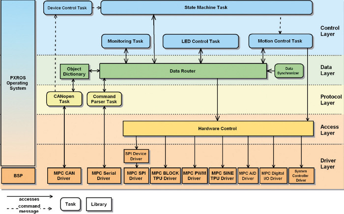
- Phytec plug-on module, carrying a MPC555 PowerPC. Based on this processor runs the PXROS real-time operating system, the motor control firmware and the digital motor driver.
- Optional PWM DC motor plug-on module, including power supply for the RMC, power drives for DC motors up to 4 ampere, current limitation, current measurement and programmable logic for safety functions.
- Optional stepper motor plug-on module, including power supply for the RMC, power drives for stepper motors up to 2.5 ampere, 2 or 5 phases, full or half step, PWM or linear operation, current limitation, programmable logic for safety functions and step pattern generation.
The configuration of a motor module will automatically be detected by the driver software; therefore, no settings are necessary, except CAN ID and limit current. The operation of RMC modules in the proximity of highly sensitive optical and electronic instrument components required to keep thermal and electromagnetic radiation as small as possible. For this purpose the stepper motor driver includes a linear mode with a second, smaller voltage in order to avoid disturbances through PWM.
An ASIC is integrated on the main board for purpose of evaluation of various encoder protocols. It supports Endat-, Incremental- and SSI-encoders.
Control Software
In Position Mode the control software provides the choice to drive with curves of second or third order. The motor drivers are designed as cascaded position and speed controllers. The software allows the activation of either a PID controller or a polynomial controller. All algorithms are implemented in floating point.
For high-speed control tasks, like step- and PWM generation, as well as step counters, intensive use has been made of the hardware-integrated motor control functions of the MPC555‘s Modular IO Systems (MIOS).
Turn-Key Development by redlogix
redlogix‘ contribution to RMC was the conception, electronics and software development up to the prototype stage, as well as integration into the VLT Control Software. By virtue of employing the standardized CANopen protocol and DS 402 profile the integration with the existing LCU software went easy and quick. Of course, we are also providing support and maintenance for these systems.