Development Tools
The implementation of the configuration software was performed with Visual Studio 2012. Because the program was required to run on all Windows versions from XP to Windows 10, the .NET Framework version 4.0 was choosen. C# was used as implementation language. In order to reuse code from the safety controller, wrappers for this C code were implemented with C / C ++.
For the graphical frontend, the Windows Presentation Foundation (WPF) was used, including its markup language XAML, with the look and feel of the GUI being defined by a design agency. Our customer provided a Mantis system for bugtracking. For internally discovered errors by our test team, a Redmine system was employed.
Features
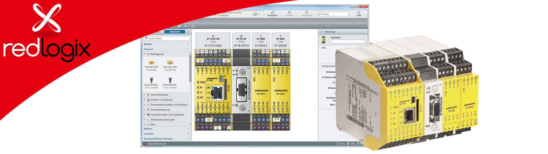
The program allows the user to configure the safety control system’s hardware and to interconnect the interfaces using a graphical logic editor. The inputs and outputs can be linked to each other via predefined function blocks (e.g. AND / OR, etc.). From the graphical representation, a binary configuration is created, which is processed by the safety controller.
The software is mainly made up of the following parts:
- hardware configuration
- logic configuration
- logic simulation, including logic analysis
- gateway configuration
- creation of configuration reports, that are needed to certify the configured safety solution
- view of the diagnostic data of the safety control system
Furthermore, for the non-safety critical part of the safety controller the Modbus protocol was implemented.
Logic Editor
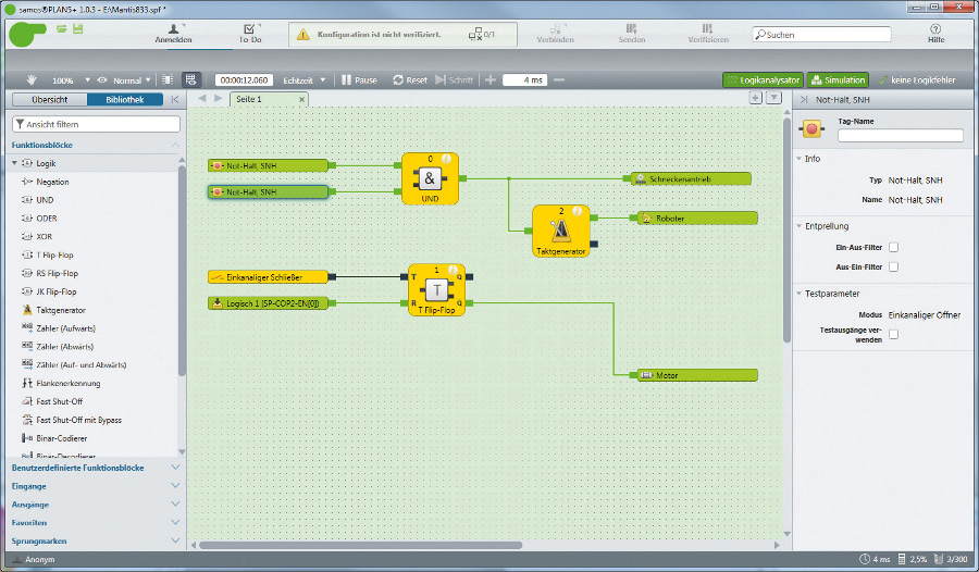
The logic editor is used to interconnect the configured inputs and outputs. For this purpose, different predefined function blocks can be hooked up with each other by drawing connection lines. The program prevents the user from creating illegal links (e.g. cycles). Several functional blocks can be grouped and saved as user-defined function blocks in libraries. All logic elements can be placed anywhere on the canvas, therefore an auto routing mechanism has been implemented in order to connect them.
Logic Simulation
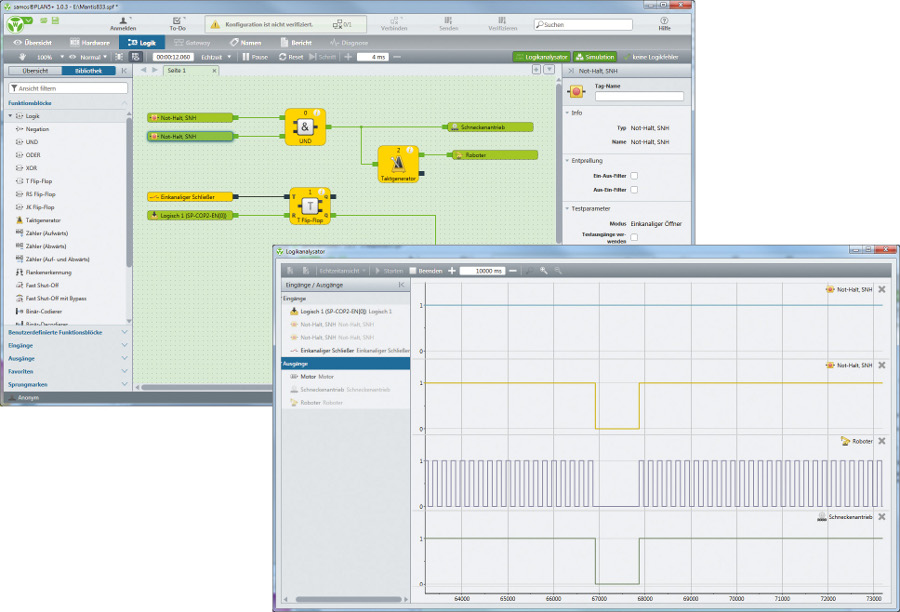
The configured program can be simulated within the logic editor. For this purpose, the original C code of the controller is used and accessed via P/Invoke. Inputs can be switched with the mouse. Furthermore, it is possible to record the status of inputs and outputs over time (logic analyzer).
Report
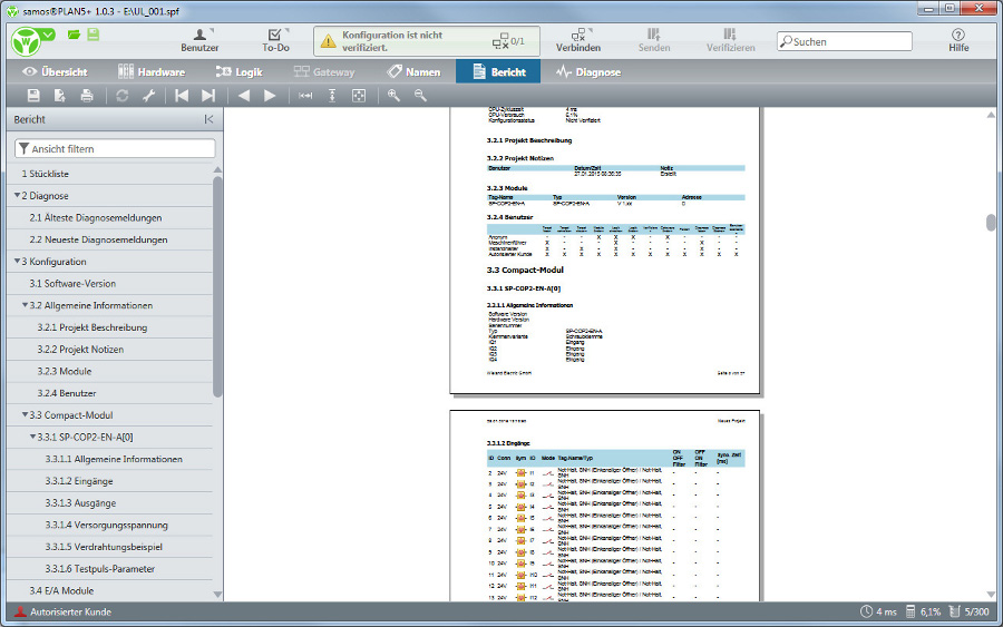
The safety controller’s purpose is to ensure the safety of a machine according to the European Machine Directive. Certified authorities check whether a machine meets these required safety demands. To support this certification process, the configuration software can create a configuration report.
Communication
For communication with the configuration software, the safety controller provides a USB, as well as an Ethernet interface. The configuration software and safety controller interact via a custom protocol that has been implemented to support the segmentation of large packages as well as integrity checking.
Other Features
In order to check the servers of the manufacturer regularly for new software versions, an update functionality was implemented. Within the project, an installer using the Wix Toolkit was created for the configuration software. It also includes the setup of the USB driver that is needed to communicate with the safety controller.
Qualification
For the qualification of the program as a level T3 tool according to DIN EN 61508, a safety concept was developed. The required unit tests and integration tests were carried out by redlogix. The unit tests were implemented using the unit test framework NUnit, for code coverage PartCover was used. For integration testing, a test sytem based on the frameworks SikuliX and Ranorex were implemented. It is used to perform automatic, semi-automatic (i. e. user guided) and manual tests. For test documentation, test reports in PDF format are automatically generated to record the results of each test step.